Selection and Design of Channel Rehabilitation Methods
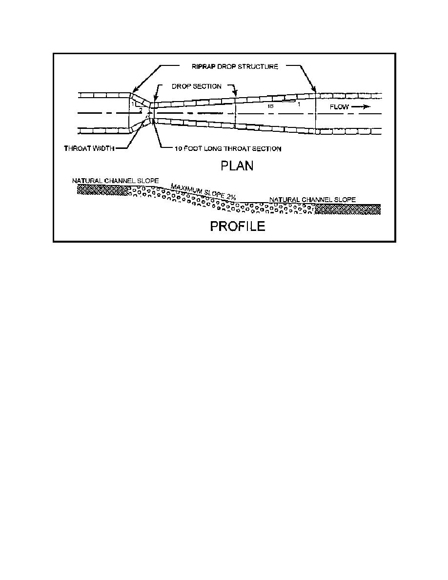
Figure 6.11 Riprap Lined Drop Structures (adapted from Tate, 1991)
of the ultimate channel morphology, both upstream and downstream of the structure which involves
assessment of sediment transport and channel morphologic processes.
The hydraulic spacing of grade control structures is a critical element of the design process,
particularly when a series of structures is planned. The design of each structure is based on the anticipated
tailwater or downstream bed elevation which, in turn, is a function of the next structure downstream.
Heede and Mulich (1973) suggested that the optimum spacing of structures is such that the upstream
structure does not interfere with the deposition zone of the next downstream structure. Mussetter (1982)
showed that the optimum spacing should be the length of the deposition above the structure that is a
function of the deposition slope (Figure 6.12). Figure 6.12 also illustrates the recommendations of Johnson
and Minaker (1944), that the most desirable spacing can be determined by extending a line from the top
of the first structure at a slope equal to the maximum equilibrium slope of sediment upstream until it
intersects the original streambed. However, each of the above references implicitly includes a specific
sediment supply concentration, and that concentration is necessary for rational designs.
Theoretically, the hydraulic spacing of grade control structures is straightforward and can be
determined by:
H = (So - Sf)x
(6.2)
220


 Previous Page
