Selection and Design of Channel Rehabilitation Methods
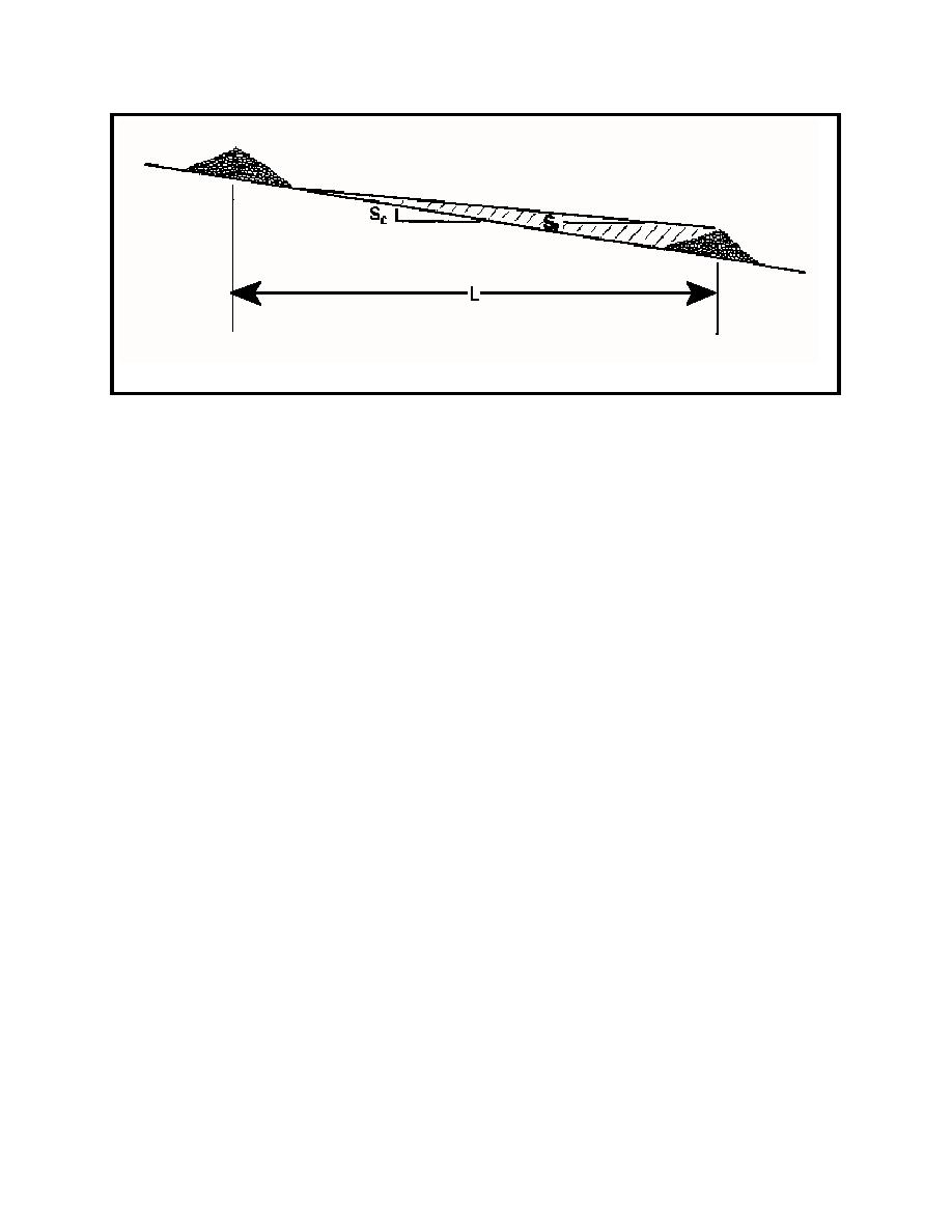
Figure 6.12 Spacing of Grade Control Structure (adapted from Mussetter, 1982)
where: H
=
the amount of drop to be removed from the reach;
So
=
the original bed slope;
Sf
=
the final, or equilibrium slope; and
x
=
the length of the reach (Goitom and Zeller, 1989).
The number of structures (N) required for a given reach can then be determined by:
N = H/h
(6.3)
where h is the selected drop height of the structure.
It follows from Eq. (6.2) that one of the most important factors when siting grade control structures
is the determination of the equilibrium slope (Sf). Failure to properly define the equilibrium slope can lead
to costly, overly conservative designs, or inadequate design resulting in continued maintenance problems
and possible complete failure of the structures. Clearly, equilibrium slope (Sf) is a function of the sediment
supply and is the slope required to transport the sediment supplied.
A critical element to designing for long-term sediment yield reduction is to explicitly include
sediment transport and sediment yield in the design process. The USACE General Design Memorandum
(GDM) No. 54 (USACE, 1990a) primarily uses a regional stability curve to design the spacing and height
of grade control structures. The regional stability curve presented as Figure 6.13 is a relationship between
thalweg slope and drainage area, and was developed by plotting the slope and drainage area of stable
channel reaches. Figure 6.13 depicts the original data, the regression of the original data, and data from
the 1995 monitoring of stream reaches. Stability was generally defined in terms of the Channel Evolution
Model (CEM) (Schumm et al., 1984) as discussed in Section 3.2. Regression of the original data used
in GDM No. 54 results in the following relationship:
221


 Previous Page
